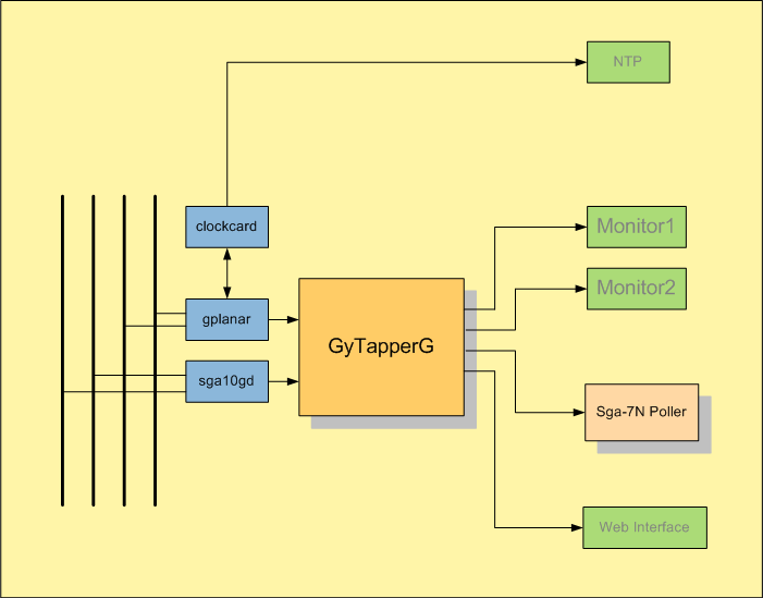
| TSP Lab | GyTapperG − Packet Capture Software | GyTapperG |
|---|
| Menu | Menuitem | Shortcut(s) | Meaning |
|---|---|---|---|
| [Log] | |||
| Find line containing... | (Ctrl-F) | Finds text in log window | |
| Find next matching line | (F3) | Finds next occurrence of text in log window | |
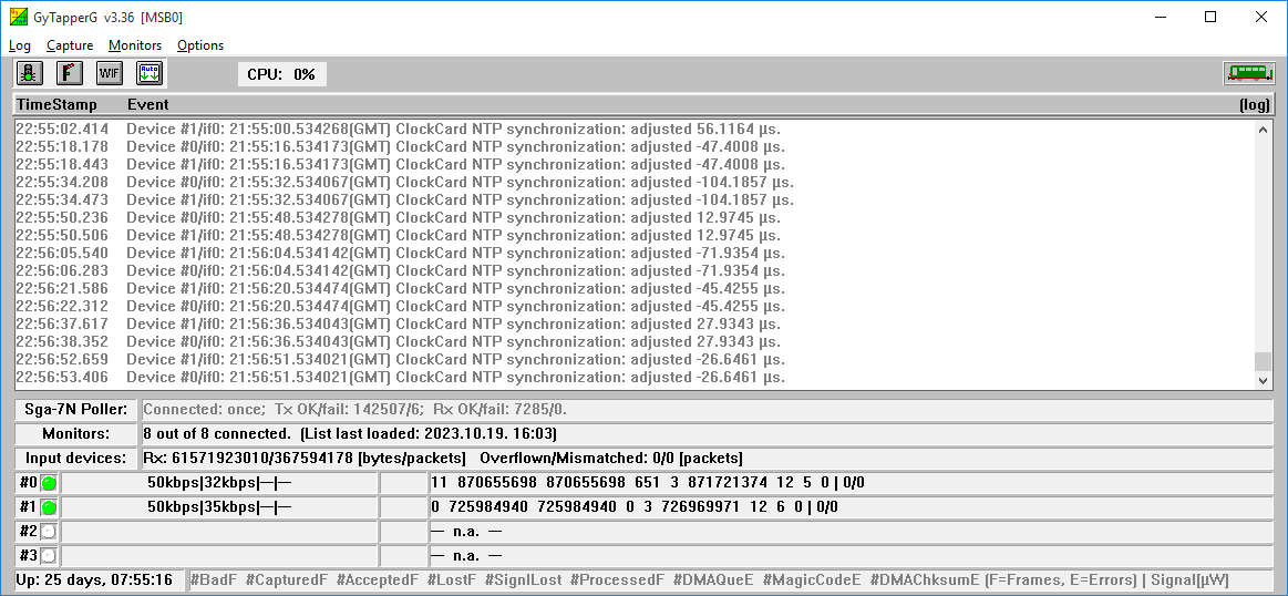
| Details | Detail level of logging (Off, Normal, Detailed, or Debug) | ||
| Flush status line counters now! | The status line counters can be flushed | ||
| Flush and zero status line counters now! | The status line counters can be flushed and cleared | ||
| [Capture] | |||
| Start/Stop capturing | (Ctrl-S or   ) )
| Capturing can be enabled or disabled | |
| Zero counter of capture devices | Capture card counters can be cleared | ||
| Reload input device list | (Ctrl-I) | Input device list can be reloaded | |
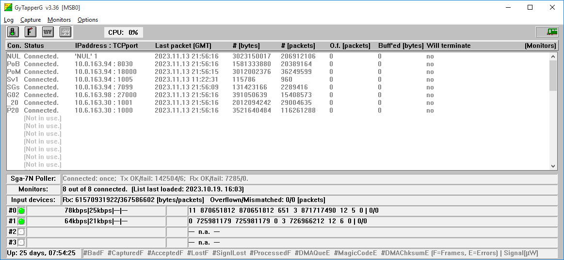
| [Monitors] | |||
| Zero all Rx counters | Rx counters can be cleared | ||
| Syntax-check list | Monitor list can be syntax-checked | ||
| Reload list | Monitor list can be reloaded | ||
| Allow auto-connect | (Ctrl-A or   ) )
| Enables automatic connection to the monitors | |
| Terminate all connections gracefully | Closes connections properly | ||
| Abort all connections immediately(!!!BRUTAL!!!) | Tears down connections immediately by breaking low layer sockets | ||
| [Options] | |||
| Auto scroll | (  ) )
| Allow automatic scrolling of the log screen | |
| Show log | (Ctrl-Tab) | Shows log screen | |
| Show Monitors | (Ctrl-Tab) | Shows Monitors screen | |
| Save settings | Saves actual settings into the configuration (INI) file |
| Button | Action |
|---|---|
|
| Disables/enables capturing ([Capture] / Start/Stop capturing menu item) |
|
| Disables/enables automatic connection to the monitors ([Monitors] / Allow auto-connect menu item) |

| Opens the status page of the web-interface in the deafult web browser |
|
| Disables/enables automatic scrolling of the log screen ([Options] / Auto scroll menu item) |
| Menuitem | Shortcut(s) | Meaning | |
|---|---|---|---|
| Zero Rx counters | Rx counters can be cleared | ||
| Terminate this connection gracefully | Closes this connection properly | ||
| Abort this connection immediately (!!!BRUTAL!!!) | Tears down this connection immediately by breaking low layer sockets |
Logging
Available on a separate page.
The web-interface
Available on a separate page.
Distribution filtering rules
Available on a separate page.
Stats and events
Available on a separate page.
IP address names
Available on a separate page.
Capture filters
Hardware level filters implemented in the cards can be used through GyTapperG module.
Each packet the card captured is supplied with a timestamp and checked against these filters.
(A 'packet' means the whole Ethernet frame with its full content.)
When a packet fits to a filter then the card passes it to the GyTapperG module through its PCI-Express interface.
GyTapperG module gets the packet and based on the distribution rules sends it to the proper monitor with a three-character LinkID.
Syntax:
[CaptureFilters Input#N/M]
| Filter definition | Meaning | ||||||||
|---|---|---|---|---|---|---|---|---|---|
[CaptureFilters Input#0/0 Input#1/* Input#3/x] | Filters are applied:
|
PASS Vlan=(5..5) | Packets with VlanID=5 are passed.
| DROP Vlan=(789..4321) IPproto=132 | Packets with VlanID between 789 and 4321 (borders are included) and IP protocol 132 are dropped.
| DROP PortSrc=5001 IPaddrSrc=(10.0.0.1..10.0.0.9) PortDst=5002 | Packets with source port 5001 from IP address between 10.0.0.1 and 10.0.0.9 (borders are included) and with destination port 5002 are dropped.
| PASS Port=23 Trunc=199 #MyNamedFilter_01 | Packets with source or destination port 23 are passed with a truncation to 199 bytes. This filter can be referred by the name "MyNamedFilter_01".
| |
| Section | Entry | Example | Meaning |
|---|---|---|---|
| [Position] | |||
| iLeft | 4 | Position of the program module on the display screen | |
| iTop | 4 | Position of the program module on the display screen | |
| iWidth | 1032 | Position of the program module on the display screen | |
| iHeight | 776 | Position of the program module on the display screen | |
| [Options] | |||
| bAutoScroll | True | Scrolls automatically the log window | |
| [Capture] | |||
| dwAutoStartWithDelay | 4 | Start of capturing is delayed with this value, given in seconds | |
| sInput#N/sCard | sga10gd0 | Capture card name and ID should be defined: sga10gd[id]. The "id" can be:
| |
| sInput#N/sLinkID | LN1 | Input device link ID used in statistics about the traffic of the interface sent to Monitor Poller | |
| sInput#N/bInternalClock | True | If 'True' then internal clock is used instead of ClockCard | |
| sInput#N/bCutCRC32 | False | If 'True' CRC32 bytes are cut from the tail of captured frames | |
| sInput#N/bLoopBack | True | If 'True' then frames seen on the Rx connector are transmitted on the Tx connector | |
| [CaptureFilters Input#0/0 Input#1/* Input#3/x] | Detailed explanation of filtering can be found in the Capture filters section. | ||
| PASS Vlan=(5..5) | |||
| DROP Vlan=(789..4321) IPproto=132 | |||
| DROP PortSrc=5001 IPaddrSrc=(10.0.0.1..10.0.0.9) PortDst=5002 | |||
| PASS Port=23 Trunc=199 #MyNamedFilter_01 | |||
| [ClockCard] | |||
| byMasterInput | 0 | Value of N from [Capture]/Input#N above | |
| dwRefreshIntervalSec | 5 | NTP time snyc interval | |
| sClockCardIPaddress | 1.2.3.9 | IP address of ClockCard | |
| sNtpServerIPaddress | 1.2.3.200 | NTP server address | |
| sGatewayIPaddress | 1.2.3.1 | Gateway address of the network which the 'ClockCardAddress' belongs to | |
| sSubnetMask | 255.255.255.0 | Mask of the subnet of 'ClockCardAddress' | |
| [Monitors] | |||
| bAllowAutoConnect | True | Enables automatic connections to the monitors | |
| wAutoConnectIntervalSec | 3 | Period of automatic (re-)connection | |
| dwMonitorMaxCount | 25 | Number of available monitor connections can be limited; default value is 50 | |
| [Sga-7N Poller] | |||
| sLocalIPAddress | 10.111.0.110 | This local IP address is used as local address during the Poller connection | |
| sRemoteIPAddress | 10.112.0.103 | IP address of the Poller machine | |
| sRemoteTCPPort | 7001 | TCP port of the Poller machine | |
| wConnectRetryDelaySec | 5 | Retrial period for establishing the Poller connection | |
| sSendThisTapperName | TAP | Tapper optionally sends a 3-character ID when connecting to the Poller (default is empty, which means not to send an ID) | |
| [Web Interface] | |||
| byDebug | 1 | If "1" then the HTTP requests are logged at Debug log level | |
| wLocalTCPPort | 8069 | TCP port number where the web-interface accepts the connection | |
| sURLForLogs | http://$$:8080/LogFiles | URL where "LogFiles" folder is available. "$$" will be replaced with IP address of the machine. "8080" is the TCP port of the FTP server. "LogFiles" is the log file folder defined in the FTP server. | |
| [Advanced] | |||
| wLogDetailLevel | 3 | Detail level of logging (Off, Normal, Detailed, or Debug) | |
| dwMaxLinesInLogWindow | 1000 | Number of lines in the log window on screen | |
| sCaption | Tapper1 | Alternative caption text for easy distinguishing amongst multiple instances of this module | |
| sLogFilesPath | c:\LogFiles | Path for the log files | |
| sIPAddrNames2file | IPAddrNames2.csv | Data file that contains IP address and name assignments | |
| [Monitor 'MN1'] | |||
| sRemoteIPAddress | 10.113.0.75 | IP address of the Monitor | |
| wRemoteTCPPort | 7001 | TCP port of the Monitor | |
| sLocalIPAddress | 10.111.0.99 | Alternative local IP address assignment for the Monitor connection | |
| bTCPKeepAlive | False | If 'True' then TCP KeepAlive feature is activated for this monitor connection | |
| bEncryptAllTraffic | True | Encryption (256-bit key AES in CBC mode) in the direction of the connected Monitor (default is False) | |
| sSendThisTapperName | TP0 | Tapper optionally sends a 3-character ID when connecting to a Monitor (or TapperPoller) (default is empty, which means not to send an ID) | |
| iTrickyTruncateRTP | 22 | Truncation and header compression settings for RTP media packets. x0 = Off, x1 = Truncate, x2 = {Truncate+Compress} 1x = only if (PortSrc^PortDst)mod4=0or1, 2x = only if (PortSrc^PortDst)mod4=2or3 | |
| L52 | 10.123.133.143 --- 10.134.133.156 : 9876 --- * | Defines the source and destination IP addresses and port values for which filtering will be done and the result will be forwarded with LinkID="L52". Detailed explanation of filtering can be found in the Distribution filtering rules section. | |
| [Monitor 'NUL' 1] | |||
| OTX | 219.239.59.104 --- 10.255.28.230 | Packets fit in this rule are simple dropped. | |