| TSP Lab
| The Sga-47 SS7 Interface Card
| Sga-47 Card
|
Wiring of Sga-47 SS7 interface card
- balanced networks -
The Backplane
Connectors on the backplane of the machine
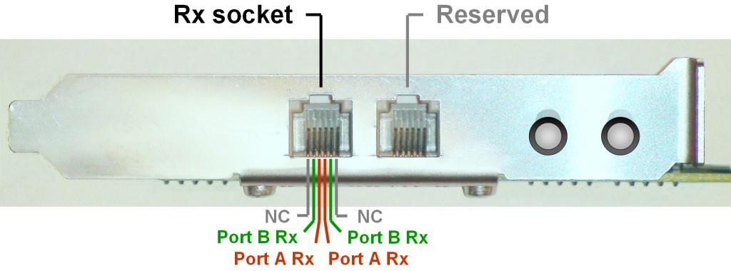
The Sga-47 interface card has two RJ12 sockets and two corresponding LEDs but only the lower ones are the relevant.
- The lower socket is used to receive two signaling PCM trunks.
The inner pair of pins is used for one PCM (A port) and the outer ones are used for the other PCM (B port).
- The upper RJ12 socket is not used, it is reserved!
- The LED indicates the state of connected PCM. (The lower LED is the relevant one,
the other one is indifferent, without reference its state.)
- Right after the PC power up, the LED is uninitialized, it is in random
state and its color has no meaning. After the application has
initialized the card, the meanings of the LED are the followings:
- no light - there is no PCM signal on the cable at all
- red - PCM signal is OK on direction Rx-A, but no PCM on Rx-B
(on the user interface of the program the A side PCM is grey, the B side is red)
- green - PCM signal is OK on Rx-B, but no PCM on Rx-A
(on the user interface of the program the A side PCM is red, the B side is grey)
- amber - PCM signal is OK on both ports (on the user interface
of the program both of the PCMs are grey)
The expansion panel has two RJ12 sockets, as well, and the upper one is for transmission of PCM trunks, the lower one is reserved.
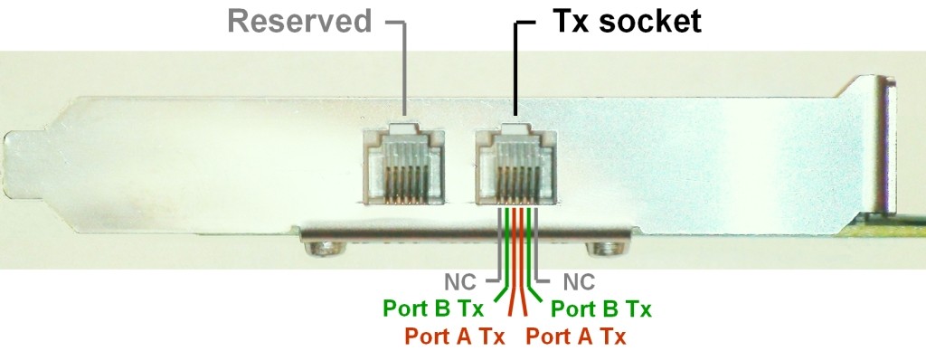
- The inner pair of pins is the transmitter side of Port A
- The outer pair of pins is the transmitter side of Port B
Connections to the signaling network
One Sga application handles one Sga-47 interface card and two signaling links (i.e. timeslots)
that are carried by two PCM trunks connected to the two ports of the card.
So, as many applications should be started on a PC as many cards are installed.
The figure below shows how to wire an Sga card to two Signaling Transfer Points.