| TSP Lab
| The Sga-47 SS7 Interface Card
| Sga-47 Card
|
Wiring of Sga-47 SS7 interface card
- unbalanced networks -
The backplane
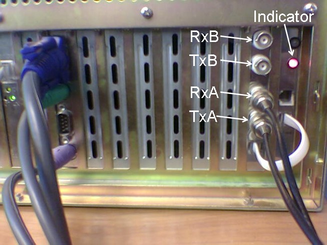
Connectors on the backplane of the machine
The Sga47 interface card has two LEDs and two RJ12 connectors:
- The LED indicates the state of connected PCM. (The lower LED is the relevant one,
the other is indifferent, without reference its state.)
- Right after the PC power up, the LED is uninitialized, it is in random
state and its color has no meaning. After the application has
initialized the card, the meanings of the LED are the followings:
- no light - there is no PCM signal on the cable at all
- red - PCM signal is OK on direction Rx-A, but no PCM on Rx-B
(on the user interface of the program the A side PCM is grey, the B side is red)
- green - PCM signal is OK on Rx-B, but no PCM on Rx-A
(on the user interface of the program the A side PCM is red, the B side is grey)
- amber - PCM signal is OK on both ports (on the user interface
of the program both of the PCMs are grey)
- The lower RJ12 connector has to be connected to the expansion panel with a short cable
(the white cable in the picture above)
- The upper RJ12 port is not used, it is reserved!
The expansion panel has the 75 ohm coaxial ports which are the followings from up to bottom:
- Rx-B - receiver port of the B interface to receive PCM signs of the remote device
- Tx-B - transmitter port of the B interface
- Rx-A - receiver port of the A interface
- Tx-A - transmitter port of the A interface
Connections to the signaling network
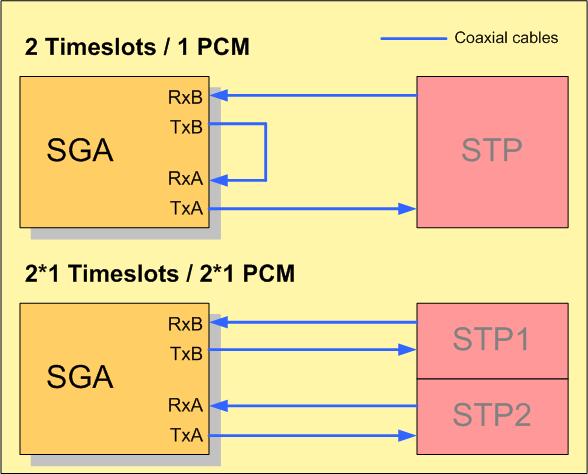
Sga applications can handle two signaling links (i.e. timeslots) that can be in a
single PCM trunk or in two separate PCM trunks (For testing purposes one signaling link is enough.)
- When the interface card connects to two separate signaling ports then the Rx-A
and Tx-A and Rx-B and Tx-B ports should be connected to the proper ports of the remote side.
- If the signaling links are in one PCM trunk then the Rx-A and Tx-B
connectors should be connected to each other with a short coaxial
cable and the cables from and to the remote device should be connected
to Rx-B and Tx-A, respectively.