| TSP Lab
| The Sga-47 SS7 Interface Card
| Sga-47 Card
|
Installation and configuration of Sga-47 SS7 interface cards
Installation of Sga-47 Card
Setting Card Base Address
Before inserting an Sga-47 interface card the base address of it should be set to the proper value.
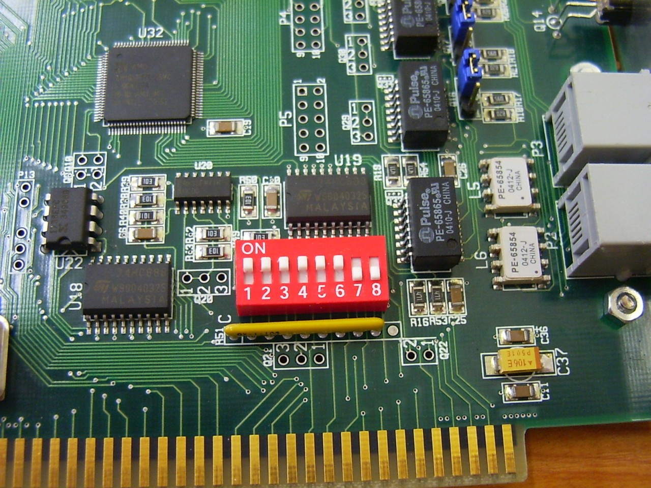
This can be done by the DIP switch on the card. When one card is used in a PC the base address always should be 0xD800.
If more cards are used, the base addresses are 0xD800, 0xD900, 0xDA00, 0xDB00 correspondingly to the order of the cards
(the first one has to has 0xD800, the second one has to has 0xD900, etc.).
| Card
| Base Address
| DIP Switch
|
| 1
| 2
| 3
| 4
| 5
| 6
| 7
| 8
|
| 1
| 0xD800
| on
| on
| on
| on
| on
| on
| off
| off
|
| 2
| 0xD900
| on
| off
| on
| on
| on
| on
| off
| off
|
| 3
| 0xDA00
| on
| on
| off
| on
| on
| on
| off
| off
|
| 4
| 0xDB00
| on
| off
| off
| on
| on
| on
| off
| off
|
The photo below illustrates how to set DIP switch for base address 0xD800.

Inserting interface cards
After the base address has set the card can be placed into a PC.
In consideration of Sga-47 cards have ISA interfaces they can only be inserted in industrial PC's equipped with ISA slots.
One active card which can transmit and receive, as well, needs two free slots, one for the card
and one other for the expansion panel.
Select the ISA slots that farthest from CPU board. Remove the corresponding and the next to it blank plates
and insert the card into the slot. The expansion panel should be placed into the adjacent free place.
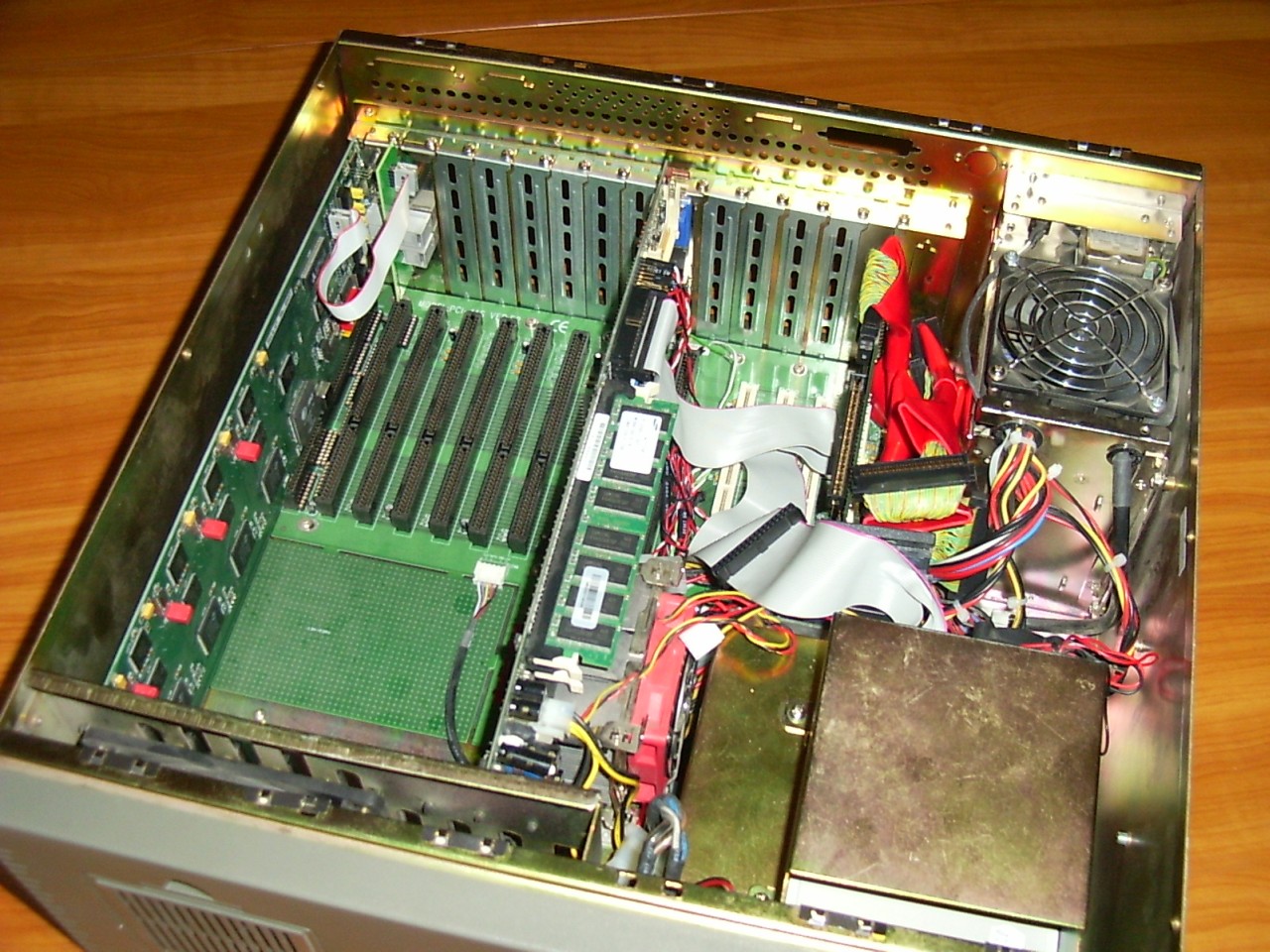
The next photo shows an industrial PC equipped with an Sga-47 card and an expansion panel.

The next step is connecting the expansion panel to the interface card using the ribbon cable
to the pins of P1 connector on the interface card.
Pay attention that the red wire should be on top of the cable!
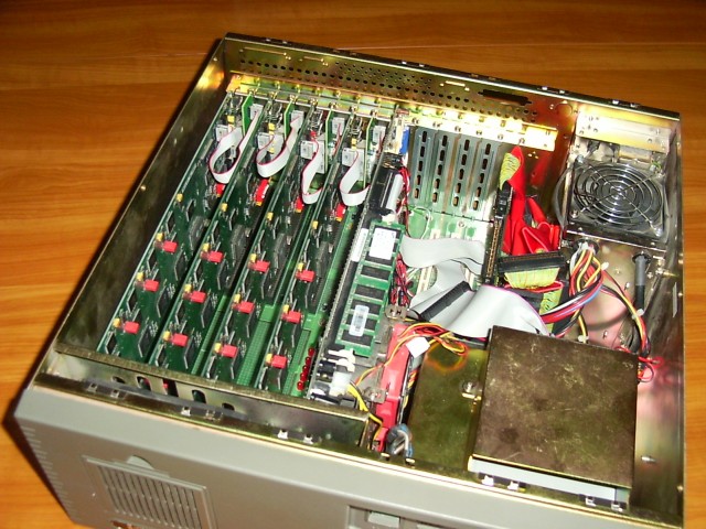
When more cards should be used in one PC first set the base address of the second card (to 0xD900)
and place it into the next place and the second expansion panel next to it. Finally connect them to each other with the ribbon cable.
For further cards the way is the same considering the position of cards and the base addresses of them.
(3rd card should have base address 0xDA00 and the 4th one should have base address 0xDB00.)

The Backplane
Connectors on the backplane of the machine
There are two types of the expansion panel of the Sga-47 interface cards. One of them is equipped with RJ12 type connectors
for the balanced 120ohm networks. The other is equipped with coaxial BNC connectors for unbalanced, 75ohm networks.
For the details of wiring see the proper sub-page of this documentation:
Although cabling depends on what type of expansion panel is used the visual indicators on the back of the Sga-47 card mean the same.
- The LED indicates the electrical and synchronization state of connected PCM's. (The lower LED is the relevant one,
the other one is indifferent, without reference its state.)
- Right after the PC power up, the LED is uninitialized, it is in random
state and its color has no meaning. After the application has
initialized the card, the meanings of the LED are the followings:
- no light - there is no PCM signal on the cable at all
- red - PCM signal is OK on direction Rx-A, but no PCM on Rx-B
(on the user interface of the program the A side PCM is grey, the B side is red)
- green - PCM signal is OK on Rx-B, but no PCM on Rx-A
(on the user interface of the program the A side PCM is red, the B side is grey)
- amber - PCM signal is OK on both ports (on the user interface
of the program both of the PCMs are grey)